

1. Theoretical Test and Analysis
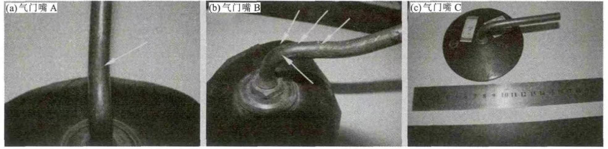
Of the 3 tire valves samples provided by the company, 2 are valves, and 1 is a valve that has not been used yet. For A and B, the valve that has not been used is marked as gray. Comprehensive Figure 1. The outer surface of valve A is shallow, the outer surface of valve B is the surface, the outer surface of valve C is the surface, and the outer surface of valve C is the surface. Valves A and B are covered with corrosion products. The valve A and B are cracked at the bends, the outer part of the bend is along the valve, the valve ring mouth B is cracked toward the end, and the white arrow between the cracked surfaces on the surface of the valve A is marked. From the above, the cracks are everywhere, the cracks are the largest, and the cracks are everywhere.
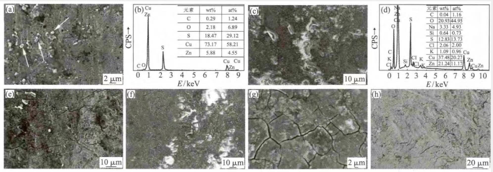
A section of the tire valve A, B, and C samples was cut from the bend, and the surface morphology was observed with a ZEISS-SUPRA55 scanning electron microscope, and the micro-area composition was analyzed with EDS. Figure 2 (a) shows the microstructure of the valve B surface. It can be seen that there are many white and bright particles on the surface (indicated by the white arrows in the figure), and the EDS analysis of the white particles has a high content of S. The energy spectrum analysis results of the white particles are shown in Figure 2(b).
Figures 2 (c) and (e) are the surface microstructures of valve B. It can be seen from Figure 2 (c) that the surface is almost entirely covered by corrosion products, and the corrosive elements of the corrosion products by energy spectrum analysis mainly include S, Cl and O, the content of S in individual positions is higher, and the energy spectrum analysis results are shown in Fig. 2(d). It can be seen from Figure 2(e) that there are micro-cracks along the valve ring on the surface of valve A. Figures 2(f) and (g) are the surface micro-morphologies of valve C, the surface is also completely covered by corrosion products, and the corrosive elements also include S, Cl and O, similar to Figure 2(e). The reason for cracking may be stress corrosion cracking (SCC) from the corrosion product analysis on the valve surface. Fig. 2(h) is also the surface microstructure of valve C. It can be seen that the surface is relatively clean, and the chemical composition of the surface analyzed by EDS is similar to that of the copper alloy, indicating that the valve is not corroded. By comparing the microscopic morphology and chemical composition of the three valve surfaces, it is shown that there are corrosive media such as S, O and Cl in the surrounding environment.
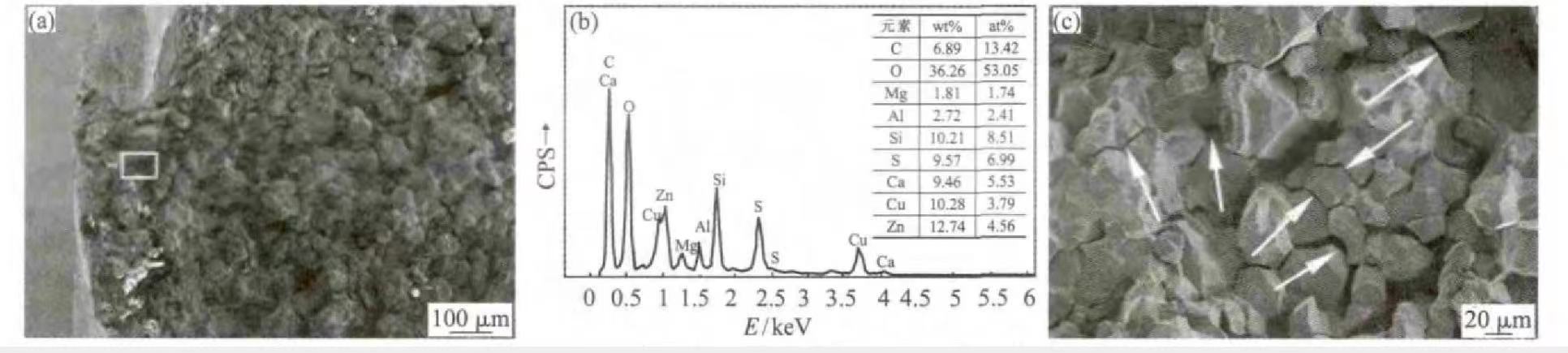
The crack of valve B was opened through the bending test, and it was found that the crack did not penetrate the entire cross-section of the valve, cracked on the side of the backbend, and did not crack on the side opposite to the backbend of the valve. The visual inspection of the fracture shows that the color of the fracture is dark, indicating that the fracture has been corroded, and some parts of the fracture are dark in color, which indicates that the corrosion is more serious in these parts. The fracture of valve B was observed under a scanning electron microscope, as shown in Figure 3. Figure 3 (a) shows the macroscopic appearance of valve B fracture. It can be seen that the outer fracture near the valve has been covered by corrosion products, again indicating the presence of corrosive media in the surrounding environment. According to energy spectrum analysis, the chemical components of the corrosion product are mainly S, Cl and O, and the contents of S and O are relatively high, as shown in Fig. 3(b). Observing the fracture surface, it is found that the crack growth pattern is along the crystal type. A large number of secondary cracks can also be seen by observing the fracture at higher magnifications, as shown in Figure 3(c). The secondary cracks are marked with white arrows in the figure. Corrosion products and crack growth patterns on the fracture surface again show the characteristics of stress corrosion cracking.
The fracture of valve A has not been opened, remove a section of the valve (including the cracked position), grind and polish the axial section of the valve, and use Fe Cl3 (5 g) +HCl (50 mL) + C2H5OH (100 mL) solution was etched, and the metallographic structure and crack growth morphology were observed with Zeiss Axio Observer A1m optical microscope. Figure 4 (a) shows the metallographic structure of the valve, which is α+β dual-phase structure, and β is relatively fine and granular and distributed on the α-phase matrix. The crack propagation patterns at the circumferential cracks are shown in Figure 4(a), (b). Since the crack surfaces are filled with corrosion products, the gap between the two crack surfaces is wide, and it is difficult to distinguish the crack propagation patterns. bifurcation phenomenon. Many secondary cracks (marked with white arrows in the figure) were also observed on this primary crack, see Fig. 4(c), and these secondary cracks propagated along the grain. The etched valve sample was observed by SEM, and it was found that there were many micro-cracks in other positions parallel to the main crack. These micro-cracks originated from the surface and expanded to the inside of the valve. The cracks had bifurcation and extended along the grain, see Figure 4 (c), (d). The environment and stress state of these microcracks are almost the same as those of the main crack, so it can be inferred that the main crack's propagation form is also intergranular, which is also confirmed by the fracture observation of valve B. The bifurcation phenomenon of the crack again shows the characteristics of stress corrosion cracking of the valve.
2. Analysis and Discussion
To sum up, it can be inferred that the damage of the valve is caused by stress corrosion cracking caused by SO2. Stress corrosion cracking generally needs to meet three conditions: (1) materials sensitive to stress corrosion; (2) corrosive medium sensitive to copper alloys; (3) certain stress conditions.
It is generally believed that pure metals do not suffer from stress corrosion, and all alloys are susceptible to stress corrosion to varying degrees. For brass materials, it is generally believed that the dual-phase structure has higher stress corrosion susceptibility than the single-phase structure. It has been reported in the literature that when the Zn content in the brass material exceeds 20%, it has a higher stress corrosion susceptibility, and the higher the Zn content, the higher the stress corrosion susceptibility. The metallographic structure of the gas nozzle in this case is an α+β dual-phase alloy, and the Zn content is about 35%, far exceeding 20%, so it has a high stress corrosion sensitivity and meets the material conditions required for stress corrosion cracking.
For brass materials, if stress relief annealing is not performed after cold working deformation, stress corrosion will occur under suitable stress conditions and corrosive environments. The stress that causes stress corrosion cracking is generally local tensile stress, which can be applied stress or residual stress. After the truck tire is inflated, tensile stress will be generated along the axial direction of the air nozzle due to the high pressure in the tire, which will cause circumferential cracks in the air nozzle. The tensile stress caused by the internal pressure of the tire can be simply calculated according to σ=p R/2t (where p is the internal pressure of the tire, R is the inner diameter of the valve, and t is the wall thickness of the valve). However, in general, the tensile stress generated by the internal pressure of the tire is not too large, and the effect of residual stress should be considered. The cracking positions of the gas nozzles are all at the backbend, and it is obvious that the residual deformation at the backbend is large, and there is a residual tensile stress there. In fact, in many practical copper alloy components, stress corrosion cracking is rarely caused by design stresses, and most of them are caused by residual stresses that are not seen and ignored. In this case, at the back bend of the valve, the direction of the tensile stress generated by the internal pressure of the tire is consistent with the direction of the residual stress, and the superposition of these two stresses provides the stress condition for the SCC.
3. Conclusion and Suggestions
Conclusion:
The cracking of the tire valve is mainly caused by stress corrosion cracking caused by SO2.
Suggestion
(1) Trace the source of the corrosive medium in the environment around the tire valve, and try to avoid direct contact with the surrounding corrosive medium. For example, a layer of anti-corrosion coating can be applied to the surface of the valve.
(2) The residual tensile stress of cold working can be eliminated by appropriate processes, such as stress relief annealing after bending.
Post time: Sep-23-2022
