

1. Brief
The internal thread used by longitudinal waves and selected to be used is fixed by ordinary bolts and self-locking bolts, calibrated by different tightening strategies, and the difference between anchor bolts and self-locking calibration anchoring characteristic curves is analyzed. Result: The bolt and bolt calibration method will obtain different calibration features, the locking time scale of the chain makes the self-calibration self-calibration and the self-calibration time-scale of the self-calibration lead to different targets. Due to the normal movement curve, the obtained different characteristic features will move to the right .
2. Test Philosophy
At present, the ultrasonic method is widely used in the bolt axial force test of the fastening point of the automobile subsystem, that is, the relationship characteristic curve (bolt calibration curve) between the bolt axial force and the ultrasonic sound time difference is obtained in advance, and the subsequent test of the actual part subsystem is carried out. The axial force of the bolt in the tightening connection can be obtained by ultrasonically measuring the sound time difference of the bolt and referring to the calibration curve. Therefore, obtaining the correct calibration curve is particularly important for the accuracy of the bolt axial force measurement results in the actual part subsystem. At present, the ultrasonic testing methods mainly include single wave method (ie longitudinal wave method) and transverse longitudinal wave method.
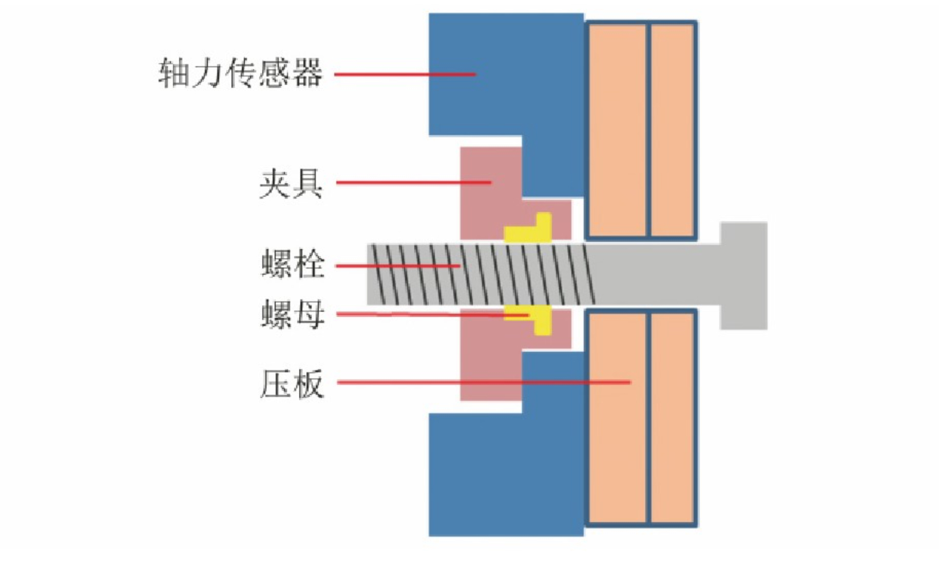
In the process of bolt calibration, there are many factors that affect the calibration results, such as clamping length, temperature, speed of tightening machine, fixture tooling, etc. At present, the most commonly used bolt calibration method is the rotation tightening method. The bolts are calibrated on the bolt test bench, which requires the production of supporting fixtures for the axial force sensor, which are the pressure plate and the internal threaded hole fixture. The function of the internal threaded hole fixture is to Replaces regular nuts. Anti-loose design is usually used in the fastening connection points with high safety factor of automobile chassis to ensure the reliability of its fastening. One of the anti-loose measures currently adopted is the self-locking nut, that is, the effective torque locking nut .
The author adopts the longitudinal wave method and uses the self-made internal thread fixture to select the ordinary nut and the self-locking nut to calibrate the bolt. Through different tightening strategies and calibration methods, the difference between the ordinary nut and the self-locking nut to calibrate the bolt curve is studied. Axial force testing of automotive subsystem fasteners makes some recommendations.
Testing the axial force of bolts by ultrasonic technology is an indirect test method. According to the principle of sonoelasticity, the speed of sound propagation in solids is related to the stress, so ultrasonic waves can be used to obtain the axial force of bolts [5-8]. The bolt will stretch itself during the tightening process, and at the same time generate axial tensile stress. The ultrasonic pulse will be transmitted from the head of the bolt to the tail. Due to the sudden change in the density of the medium, it will return along the original path, and the surface of the bolt will receive the signal through the piezoelectric ceramic. time difference Δt. The schematic diagram of ultrasonic testing is shown in Figure 1. The time difference is proportional to the elongation.
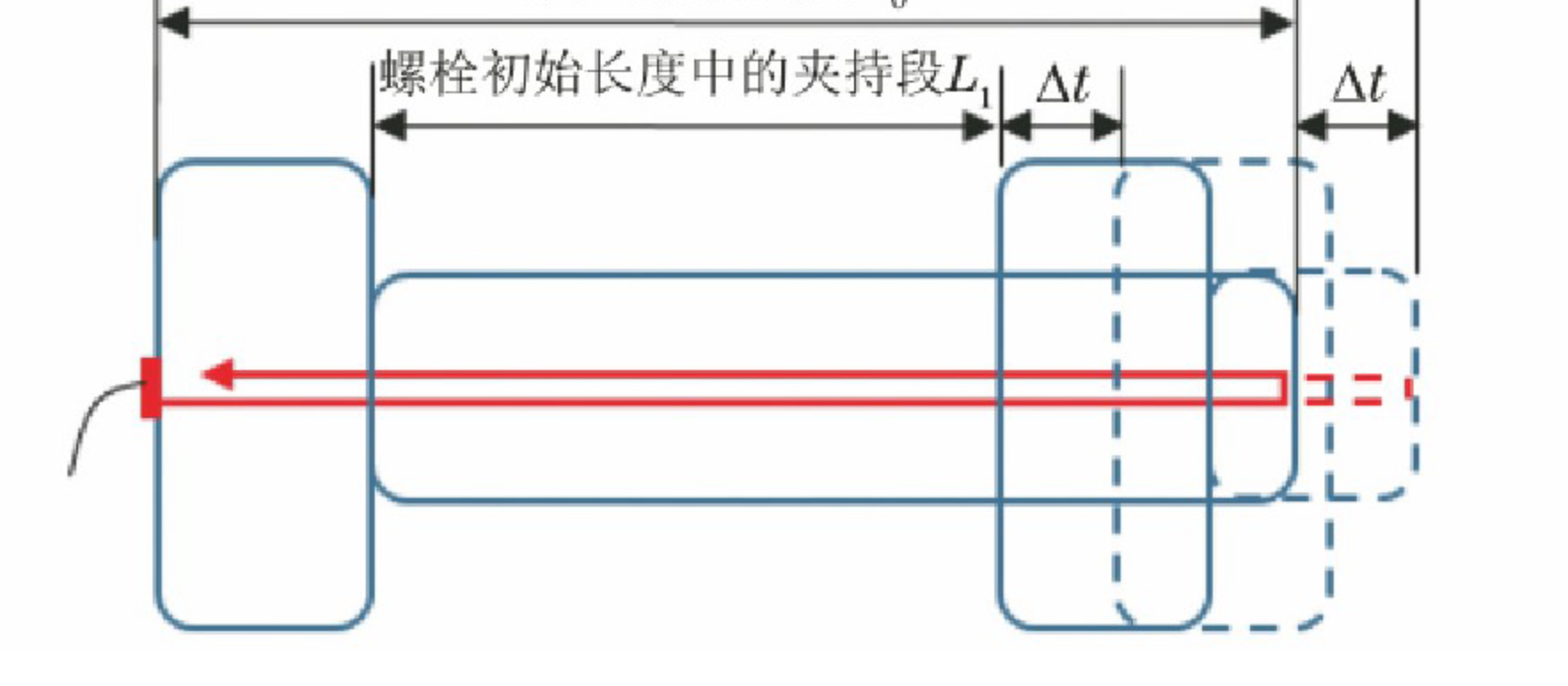
Testing the axial force of bolts by ultrasonic technology is an indirect test method. According to the principle of sonoelasticity, the speed of sound propagation in solids is related to the stress, so ultrasonic waves can be used to obtain the axial force of bolts. The bolt will stretch itself during the tightening process, and at the same time generate axial tensile stress. The ultrasonic pulse will be transmitted from the head of the bolt to the tail. Due to the sudden change in the density of the medium, it will return along the original path, and the surface of the bolt will receive the signal through the piezoelectric ceramic. time difference Δt. The schematic diagram of ultrasonic testing is shown in Figure 1. The time difference is proportional to the elongation.
M12 mm × 1.75 mm × 100 mm and then the specification of the bolts, use ordinary bolts to fix 5 such bolts, first use the self-anchor test with different forms of calibration solder paste, it is artificial spiral plate to bolt flange fit and press When scanning the initial wave (that is, recording the original L0), and then screw it to 100 N m+30° with one tool (called the type I method), and the other is to scan the initial wave and screw it to the target size with a tightening gun (called the type I method). For the second type method), there will be a certain type in this process (as shown in Figure 4) 5 is the ordinary bolt and the self-locking method The curve after calibration according to the type I method Figure 6 is the self-locking type. Figure 6 is a self-locking class. Class I and Class II curves. The method of use can be, use the custom curve of the common anchor anchor class, exactly the same (all pass through the origin with the same segment rate and number of points); lock the index type of the anchor point type (type I and anchor mark, the slope of the interval difference and the number of points); get similarities)
Experiment 3 is to set the Y3 coordinate of Graph Setup in the data acquisition instrument software as the temperature coordinate (using an external temperature sensor), set the idling distance of the bolt to 60 mm for calibration, and record the torque/axial force/temperature and the curve of the angle. As shown in Figure 8, it can be seen that with the continuous screwing of the bolt, the temperature is rising continuously, and the temperature rise can be regarded as linear. The four bolt samples were selected for calibration with self-locking nuts. Figure 9 shows the calibration curves of the four bolts. It can be seen that the four curves are all translated to the right, but the degree of translation is different. Table 2 records the distance that the calibration curve shifts to the right and the temperature increase during the tightening process. It can be seen that the degree of the calibration curve shifting to the right is basically proportional to the temperature increase.
3. Conclusion and Discussion
The bolt is subjected to the combined action of axial stress and torsional stress during tightening, and the resultant force of the two eventually causes the bolt to yield. In the calibration of the bolt, only the axial force of the bolt is reflected on the calibration curve to provide the clamping force of the fastening subsystem. It can be seen from the test results in Figure 5 that, although it is a self-locking nut, if the initial length is recorded after the bolt has been manually rotated to the point where it is about to fit the bearing surface of the pressure plate, the calibration curve results are completely coincident with those of the ordinary nut. This shows that in this state, the influence of the self-locking torque of the self-locking nut is negligible.
If the bolt is directly tightened into the self-locking nut with an electric gun, the curve will shift to the right as a whole, as shown in Figure 6. This shows that the self-locking torque affects the acoustic time difference in the calibration curve. Observe the initial segment of the curve shifted to the right, indicating that the axial force is still not generated under the condition that the bolt has a certain amount of elongation, or the axial force is very small, which is equivalent to that the bolt has not been pressed against the axial force sensor. Stretching, obviously the elongation of the bolt at this time is false elongation, not real elongation. The reason for false elongation is that the heat generated by the self-locking torque during the air tightening process affects the propagation of ultrasonic waves, which is reflected on the curve. It shows that the bolt has been elongated, indicating that the temperature has an effect on the ultrasonic wave. For Figure 6, the self-locking nut is also used for calibration, but the reason why the calibration curve does not shift to the right is that although there is friction when screwing in the self-locking nut, heat is generated, but the heat has been included in the recording of the initial length of the bolt. It has been cleared, and the bolt calibration time is very short (usually less than 5s), so the effect of temperature does not appear on the calibration characteristic curve.
It can be seen from the above analysis that the thread friction in the air screwing causes the bolt temperature to rise, which reduces the ultrasonic wave velocity, which is manifested as a parallel shift of the calibration curve to the right. Torque, both of which are proportional to the heat generated by thread friction, as shown in Figure 10. In Table 2, the magnitude of the right shift of the calibration curve and the temperature increase of the bolt during the whole tightening process are counted. It can be seen that the magnitude of the right shift of the calibration curve is consistent with the degree of temperature increase, and has a linear proportional relationship. The ratio is about 10.1. Assuming that the temperature increases by 10°C, the acoustic time difference increases by 101ns, corresponding to the axial force of 24.4kN on the M12 bolt calibration curve. From a physical point of view, it is explained that the increase of temperature will cause the resonant property of the bolt material to change, so that the ultrasonic wave speed through the bolt medium changes and then affects the ultrasonic propagation time.
4. Suggestion
When using ordinary nut and self-locking nut to calibrate the characteristic curve of the bolt, different calibration characteristic curves will be obtained due to different methods. The tightening torque of the self-locking nut increases the temperature of the bolt, which increases the ultrasonic time difference, and the obtained calibration characteristic curve will shift to the right in parallel.
During the laboratory test, the influence of temperature on the ultrasonic wave should be eliminated as much as possible, or the same calibration method should be adopted in the two stages of bolt calibration and axial force test.
Post time: Oct-19-2022
