

1. Structural Characteristics Of Workpiece
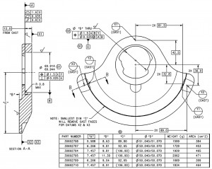
The shape of the workpiece thin-walled wheel weights is a fan shape, the material is QT600, the hardness is 187-255 HBW, the inside is a special-shaped hole, and the thinnest part is only 4 mm thick. The dimensional accuracy requirements of the balance block are shown in Figure 1. The diameter of the center hole B benchmark is Φ69.914-69.944 mm, and the tolerance is only 0.03 mm. Below is a profiled blank hole. Intermittent cutting is performed when machining the C reference hole and the outer circle. The wall thickness here is only 4 mm, which is easy to generate cutting stress and deformation and affect the tolerance size of the B reference hole, which is a difficult point in workpiece processing.
2. Hidden Dangers Of Traditional Craft
Thin-walled parts are easily deformed during the milling process, mainly due to the deformation caused by cutting stress and clamping . The traditional processing scheme is processed by CNC machining center and CNC lathe, which is divided into two processes. One is the OP10 process. Use a Φ60 mm disc milling cutter to rough and finish the upper plane to the size of the drawing, use a Φ20 mm alloy milling cutter to rough mill the inner hole Φ51.04-51.07 mm to Φ50.7 mm (leave 0.3-0.4 mm), use a Φ20 mm Alloy milling cutter rough milling inner hole Φ69.914~69.944 mm to Φ69.6 mm (leave 0.3~0.4 mm), fine boring inner hole Φ51.04~51.07 mm and Φ69.914~69.944 mm with fine boring cutter, drill 2 ×Φ18 mm with two small holes. The second is the OP20 process. The outer circle "C" of the rough and fine turning is to the technical requirements of the drawing.
The machining difficulty of the wheel weights, the reference hole B, was machined to the size required by the drawing in the OP10 process. Remove the workpiece and measure the diameter of the reference hole B, Φ69.914~69.944 mm, and the ovality error is 0.005~0.015 mm, and the size meets the requirements of the drawing. However, after the OP20 is processed, remove the workpiece and measure the diameter of the reference hole of B, Φ69.914-69.944 mm, and the ovality error is 0.03-0.04 mm. It can be seen that the diameter has exceeded the requirements of the drawing .
3. Solution
Improve tooling. Whether the design of the clamping device is correct has a direct impact on ensuring the machining accuracy of the workpiece, improving labor productivity and reducing the labor intensity of workers . Due to the characteristics of thin-walled parts, excessive clamping force or uneven force will cause elastic deformation of the workpiece, which will affect the accuracy of the size and shape tolerance of the part, and eventually lead to the size of the processed part being out of tolerance. In order to solve this problem, the model and size of the clamping cylinder and the support cylinder should be carefully selected when designing the hydraulic tooling.
Post time: Aug-19-2022
