



- TPMS valve stems come in exactly two construction families — rubber snap-in and clamp-in aluminium — and they are not interchangeable on the same rim hole.
- Four variables decide compatibility: the sensor generation, the rim valve hole diameter, the sealing system, and the mounting fastener torque.
- The published T-10 screw torque on a TRW Version 4 sensor is 12.5 inch lbs, which is 1.4 N&m, and over-torquing that fastener is a leading cause of a leak that returns after the vehicle is back in service.
- A clamp-in aluminium valve seals through separate rubber washers, an aluminium nut and a seat, so a missing washer is a leak, not a detail.
- Rubber valves age through weather exposure, so we recommend replacing the valve every time a tire is changed rather than replacing it when the dashboard light appears.
- For a mixed fleet, specify from the sensor outward — never from the vehicle model year or the rim bolt circle.
To specify TPMS valve stems for a mixed fleet without compatibility failures, you must classify every wheel by valve construction, record the sensor generation and its mounting torque, and match the valve to the sensor rather than to the rim. A TPMS valve is a pressure-retaining part that connects the sensor to the wheel rim, and it comes in two construction families: a rubber snap-in stem that pulls through the rim hole and seals with its own elastomer body, and a clamp-in aluminium stem that seals through separate components. Because the two families seal differently, a valve that works in one rim hole pattern will not necessarily seal in another, which is why a fleet running both types cannot be supplied from a single line item.
On TRW Version 4 sensors, the published T-10 screw torque is 12.5 inch lbs, which is 1.4 N&m. That single figure is the fastest way to identify which sensor family you are holding in your hand. On a clamp-in aluminium valve, the sealing stack is rubber washers plus an aluminium nut plus a seat, so a missing or damaged washer is a leak. On a rubber snap-in stem, the qualified EPDM rubber body itself is the seal, so pull-through force and rubber compound decide whether it holds. We build and test to ISO/TS 16949, and every unit in our TPMS rubber snap-in range is tested before shipping, because a tire valve is a safety-critical component and low-quality valves can cause rapid deflation with vehicles becoming uncontrollable.
What Are the Two TPMS Valve Families, and Why Are They Not Interchangeable?
A TPMS valve stem is the pressure-retaining component that connects the sensor to the wheel rim, and it is built in one of two families: rubber snap-in or clamp-in aluminium. Both serve the same purpose, which is to keep the tire’s air pressure stable, but they achieve it with different parts, different tools and different failure modes.
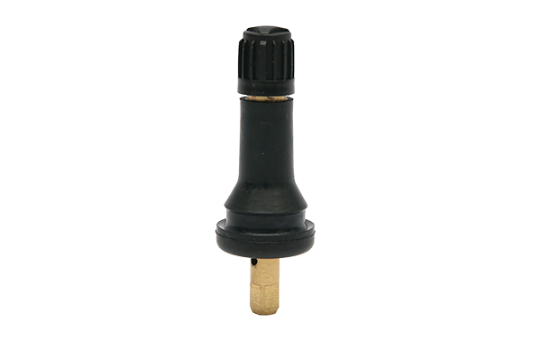
A rubber snap-in stem seals with its own elastomer body. The stem is pulled through the rim hole from the inside and the rubber flares behind the rim, so the pull-through force and the rubber compound decide the seal. Our TPMS-2 tire pressure sensor rubber snap-in valve stems use qualified EPDM rubber specifically because it gives a consistent pull force across temperature, which matters when a technician is fitting four wheels by feel in a cold bay.
Because the pull force has to feel the same at 5°C and at 35°C, the rubber compound is not a materials preference, it is an installation control. EPDM holds its elastic behaviour across that range better than the alternatives we have tested, which is why qualified EPDM rubber is the feature we lead with rather than bury in a datasheet. A rubber that is stiff on a cold morning takes more force to seat and can be pulled incorrectly, and a rubber that is soft on a warm afternoon can seat without the flange fully engaging. Neither looks wrong during fitting. Both show up weeks later as a slow leak.
The installation method matters more than most buyers expect, and it is worth stating plainly. A pull-through stem is fitted from the inside of the rim in a single movement, with the sensor already located correctly, and the valve is then seated by pulling the stem until the flange is fully engaged behind the rim. Because the engagement is felt rather than measured, the technician’s judgement is part of the seal, and that is the real reason we test every unit before shipping rather than sampling. A valve that seats correctly every time can be replaced with confidence. One that seats half the time cannot.
A clamp-in aluminium valve seals through separate components. Inside the stem, a brass or aluminium core controls airflow, and rubber washers, an aluminium nut and a seat seal the sensor properly to the rim. Because the seal is distributed across several parts, a clamp-in valve fails when one component is missing, distorted or tightened unevenly, and the failure looks identical to a bad valve when the vehicle comes back with a slow leak.
The multi-part stack is where I would focus a new buyer’s attention, because it is the only place where a valve can be assembled incorrectly and still look correct. A technician who has fitted clamp-in valves for twenty years will have the sequence in their hands and will not check it. A technician who does this occasionally will assemble a valve that is missing its seat, and nothing about the finished wheel will reveal that. Because the missing component is not visible once the wheel is mounted, the error is discovered by the customer rather than by the shop, which is the worst possible place to discover it.
Let me be fair to the aluminium valve here, because it is often dismissed unfairly. A clamp-in aluminium valve has real advantages in service: the metal body does not age, the sealing components are individually replaceable, and the assembly is verifiable by eye at each step. Because those advantages are genuine, my preference for rubber snap-in construction in volume replacement work is a preference about consistency of installation, not a claim that aluminium is inferior. Where a technician is being trained, where components are being inspected, or where the wheel design calls for it, clamp-in is the right answer and I would not argue otherwise.
My position on this, stated plainly: I would rather a fleet runs two clean line items than one compromise line item that fits “most” wheels. Two families means two part numbers, two bin locations and two clear cross-reference records. One compromise line item means an ambiguity that surfaces at the tire bay, and it surfaces at the tire bay because that is where the wheel is off.
Which Four Variables Actually Decide Compatibility?
Four variables decide whether a TPMS valve stem will fit and hold: the sensor generation, the rim valve hole diameter, the sealing system, and the mounting fastener torque. I say this from the position of a manufacturer that has been building valves since 1996 and that now ships into OEM and aftermarket programmes across the Americas, Europe, Japan, Asia and Oceania.
| Variable | What it decides | How it fails when specified wrong |
|---|---|---|
| 1. Sensor generation | The valve core profile that passes through the sensor housing, and therefore which catalogue cross-reference is valid. | The stem physically will not pass through the sensor housing, or it passes but does not seat, producing an intermittent leak that appears only when hot. |
| 2. Rim valve hole diameter | The bore the stem passes through, and therefore whether a snap-in flange seats flat behind the rim. | The flange seats on the edge of the hole rather than flat, so the seal is a line contact instead of a face contact and the valve works loose. |
| 3. Sealing system | Which components create the seal: the elastomer body on a rubber snap-in, or washers, nut and seat on a clamp-in. | A clamp-in valve assembled without its washers or seat leaks steadily, and it is often misdiagnosed as a failed sensor. |
| 4. Mounting fastener torque | The clamping load that holds the assembly in the rim, expressed as the sensor’s specified T-10 screw torque. | Under-torquing leaves a slow leak; over-torquing distorts the seal face and produces the same slow leak, discovered only after the vehicle is back on the road. |
Because these four variables are independent of each other, a valve can be correct on three of them and still fail on the fourth. That is the specific reason mixed fleets fail. A fleet that grew by acquisition carries wheels from four or five model generations, and the rim hole diameter on a wheel is not the same as the sensor generation on the tire.
Let me give you the failure I see most often, because it is not the one people expect. It is not the dramatic catastrophic leak. It is a valve that fits the sensor correctly, seats correctly, and still loses pressure slowly after several weeks because the rim valve hole on that specific wheel is not the diameter the valve was designed to seal against. Because the valve seats on the edge of the hole instead of flat behind the rim, the contact is a line rather than a face, and a line contact will hold for a while and then will not. The tire goes soft on a warm afternoon, the tire goes hard again overnight, and the technician cannot reproduce it in the bay because it only fails once the wheel is warm and loaded.
What makes this failure expensive is not the valve, it is the diagnostic time. A part that is technically correct for the sensor sends the whole investigation in the wrong direction, because everyone stops looking once the part number matches. Because the sensor keeps transmitting throughout, there is no TPMS warning either, so the customer and the technician are both looking for a fault in a system that is working exactly as designed. We have had customers come back to us convinced the sensor was defective when the actual issue was the rim valve hole on one axle.
The honest lesson, and I say this without any satisfaction, is that the third variable is the one people skip. Sensor generation and torque are checkable against a published figure, so they get checked. Rim valve hole diameter is not printed anywhere the technician is standing, so it does not get checked. Because it is the only variable on this list that requires touching the wheel, it is the one that gets skipped under time pressure, and it is the one that determines whether the other three were worth doing.
Why Does the Torque Figure Identify the Sensor Family So Quickly?
The specified T-10 screw torque identifies the sensor family faster than any other single figure, because torque specifications are not shared between sensor generations. On TRW Version 4 sensors, the specified T-10 screw torque is 12.5 inch lbs, which is 1.4 N&m, and that figure appears in the application data for the rubber snap-in valve designed to pair with it.
Because the torque value is quoted per sensor generation rather than per valve type, holding a valve that carries a different figure in your hand is the first evidence that the part is wrong. In our experience the technician who checks torque before anything else catches the mismatch at the counter, while the technician who fits first discovers it at the road test, and by then the wheel is already mounted and the vehicle is already released.
Because torque figures are published by sensor manufacturers and they change between generations, sometimes by a small amount and sometimes substantially, I would not publish a table of figures I cannot stand behind. What we publish is the figure for the pairing we actually build and test. If your fleet runs a sensor generation we do not build against, the correct response is to check that sensor’s own specification, not to assume our nearest figure is close enough. Torque is not a dimension you round.
There is a second reason I insist on this, and it is about over-torquing specifically. Under-torquing produces a leak that shows up quickly, often on the drive home from the shop. Over-torquing produces a leak that shows up in three weeks, because the seal face has been distorted just enough to leak under load and heat. Because the over-torque leak arrives late, it is the one that gets misattributed to the sensor, and the sensor gets replaced, and the valve gets replaced again, and the rim hole diameter still has not been checked. I have seen that sequence run three times on the same vehicle.
What I would put in your work order, if I were writing it, is the figure and the tool. A torque value with no tool specified is not a control, it is a wish. Because a click-type wrench at its lowest setting and a digital wrench set to 12.5 inch lbs do not deliver the same clamping load on the same fastener, the tool is part of the specification rather than an implementation detail, and it is the part that gets left out most often.
Which Cross-References Actually Carry Over to a Mixed Fleet?
A published cross-reference is only valid within one sensor family, so the reliable ones are the ones that carry a valve geometry rather than a brand name. On our TPMS-2 rubber snap-in valve stems, the reference part numbers we publish are Schrader kit 20635 and Dill kit 20635′s companion, Dill kit VS-65, and the application data carries the T-10 screw torque of 12.5 inch lbs (1.4 N&m) for the TRW Version 4 sensor.
Because a cross-reference describes valve geometry rather than a brand name, two references that resolve to the same geometry are genuinely interchangeable. That is the test I would apply to any cross-reference you are given: ask what physical dimension it is describing. Because a reference that matches on brand name alone is not a compatibility statement, it is a guess someone wrote down once and nobody has revisited since. I would rather a buyer had no cross-reference at all than a confident one that describes nothing.
Let me tell you what a good cross-reference record looks like in practice, because buyers rarely get one. It names the valve family, names the sensor generation it belongs to, gives the mounting torque figure, and gives at least one geometric feature that a technician could verify by eye with the wheel in hand. Because a record with all four can be checked at three different points in the process, it catches errors at the counter instead of at the road test. That is the whole value of the exercise.
And here is the part that frustrates me as a manufacturer, so I will say it plainly. Too many cross-references in this trade were built from what was convenient to type rather than from what was measured. Because an unverified reference propagates: it gets copied into a distributor’s catalogue, then into a fleet matrix, then into a worker’s memory, and by then it has the authority of a fact. We publish ours per pairing deliberately, knowing it makes our catalogue look less universal. I would rather our data be narrow and correct than broad and approximately right.
What Does Rubber Snap-In Versus Clamp-In Aluminium Cost You in Service?
The two families differ most in service life and in what happens at the tire bay, not in the purchase decision. Rubber valves are exposed to different weather conditions throughout the year, which leads to aging over time, so we recommend replacing the valve every time a tire is changed.
Because rubber ages through weather exposure rather than through a single mechanical event, the failure arrives gradually and the diagnostic evidence is weak, which is why we prefer a fixed replacement rule to a fault-driven one. A clamp-in aluminium valve, by contrast, tends to fail through a specific assembly error, and that error is visible at assembly if the technician checks the stack.
Because the aging is gradual, replacing the valve every time a tire is changed converts an unpredictable failure into a scheduled task, and it also means the sensor pairing gets verified at every tire change, which is the earliest possible moment to catch a mismatch.
I have watched this rule earn its keep more than once. A distributor in Northern Europe was losing roughly one return for every batch of four wheels that came back, and we spent a full season looking at sensor generations before anyone suggested simply replacing the valve at every tire change instead of replacing it when the dashboard complained. Because the dashboard almost never complains, a valve that has been aging for two years keeps inflating quietly until the tire is visibly soft, and by then the tire has usually been damaged as well as the valve. The rule costs one part per tire change. The alternative costs the tire.
How Do You Build a Mixed-Fleet Part Matrix That Survives an Acquisition?
A mixed-fleet matrix survives when it is keyed by sensor generation rather than by vehicle model, because model years get rebadged and sensor generations do not. I have watched distributors organise stock by make and model, and then lose a whole delivery because a mid-year production change altered the sensor on one trim level only.
Because sensor generations are stable identifiers, keying the matrix by sensor generation means a new vehicle added to the fleet is matched by checking one part number rather than by researching a model year. Because we publish cross-references per pairing, the matrix has a verifiable basis rather than a distributor’s recollection, and that is what makes it defensible when someone audits the stock room.
Let me describe the actual failure I have seen, because it is not a dramatic one. A distributor organised stock by make and model for years. It worked perfectly until a manufacturer changed the sensor on one trim level mid-production-year, which is a routine manufacturing decision. Because the model key did not change, the old valve stayed in the same bin, the new vehicle was matched by model, and an entire pallet went out to four customers before anyone noticed. Nothing about the ordering system had malfunctioned. The key was simply too coarse for the variation it was being asked to carry.
My rule of thumb, and it has held up for us across many catalogues: if a key cannot be checked by looking at the wheel, it is not a key. Sensor generation can be checked by reading the sensor. Rim valve hole diameter can be checked with a gauge. Valve construction family can be checked by eye. Because all three are verifiable at the bay, a matrix built on them can be audited by the people actually doing the work, and that is the property that keeps a matrix correct after the person who built it has left.
I would also add one column most matrices do not have: the date the record was last confirmed against a physical sample. Because a cross-reference that has not been verified against an actual valve in five years is a memory rather than a measurement, and the date makes that visible to anyone auditing the file, which turns an invisible degradation into a scheduled check.
| Matrix key | What it controls | What it prevents |
|---|---|---|
| Valve construction family | Whether the part is a rubber snap-in or a clamp-in aluminium stem. | It prevents a single compromise line item being used across both families, which is the most common cause of a mixed-fleet failure. |
| Sensor generation | Which valve core profile passes through the sensor housing, and therefore which cross-reference applies. | It prevents a cross-reference being carried across sensor families, which is where most “it looks the same” purchases go wrong. |
| Rim valve hole diameter | Whether the snap-in flange seats flat behind the rim. | It prevents a valve that fits the sensor but seats on the edge of the rim hole and works loose in service. |
| Sealing component set | Which washers, nut and seat ship with a clamp-in valve, or whether the elastomer body is the only seal on a snap-in. | It prevents a clamp-in valve being assembled without its sealing stack, which produces a steady slow leak. |
| Specified mounting torque | The T-10 screw torque value recorded against the sensor generation on the work order. | It prevents under-torque and over-torque, the two errors that produce the same leak symptom from opposite causes. |
Which Specification Should You Choose?
Choose a rubber snap-in stem when the wheel has a rim hole sized for a pull-through stem, the sensor generation is known, and you want the seal to come from a single qualified elastomer body rather than a multi-part stack. That is the majority of passenger and light commercial fitments, and it is why rubber snap-in valves remain the volume construction in replacement markets.
Choose a clamp-in aluminium stem when the rim and sensor are designed for a clamped assembly, when the sealing components must be replaced individually, or when the valve must be serviced without replacing the whole stem. Choose both when your fleet genuinely runs both families, and accept that the part file has two lines rather than one.
My honest advice for a mixed fleet: specify the valve from the sensor outward, and let the rim hole be a check rather than the starting point. Starting from the vehicle or the rim is how the industry ends up with “fits most applications” in a catalogue, and “fits most” is the same sentence as “does not fit yours”.
Choose a rubber snap-in stem when the seal should come from one qualified part
Choose a rubber snap-in stem when the rim hole is sized for a pull-through stem, the sensor generation is known, and you would prefer a single qualified elastomer body rather than a multi-part stack. That covers the majority of passenger and light commercial fitments, and it is why rubber snap-in valves remain the volume construction in replacement markets. Because the whole seal is one component, there is no assembly sequence to get wrong, which matters most where technicians rotate between brands rather than specialising in one.
Choose a clamp-in aluminium stem when the design calls for a clamped assembly
Choose a clamp-in aluminium stem when the rim and sensor are designed for a clamped assembly, when sealing components must be replaceable individually, or when the valve has to be serviced without replacing the whole stem. Because the metal body does not age with weather exposure, the ageing variable disappears and the maintenance question becomes inspection rather than replacement. For fleets with harsh coastal or high-UV duty cycles, that is a real argument, and I would not dismiss it.
Choose both when your fleet genuinely runs both families
Choose both when your fleet genuinely runs both families, and accept that the part file has two lines rather than one. Because the two lines cost almost nothing to carry and the single compromise line costs a returned wheel, I would always carry both. The compromise line only pays for itself on a fleet small enough that the extra bin slot matters more than the failure rate, and fleets that small are not usually running mixed populations.
Do not specify from the vehicle model year
Do not specify from the vehicle model year, because model years get rebadged across production runs while sensor generations stay stable. Because a mid-year sensor change on one trim level leaves every model-keyed record still looking correct, the model year is the one key that fails silently. I would rather your record be slightly harder to complete than silently wrong, and that is the entire argument for keying by sensor generation.
How to Specify TPMS Valve Stems in Five Steps
Five steps give a repeatable specification that a distributor, a warehouse and a tire bay can all execute without asking the same question three times. The order matters: classification before measurement, measurement before matching.
Because each step is verifiable by the person doing it, the method does not depend on anyone being especially knowledgeable, and that is the property that matters when the person doing it is on a tire bay at four in the afternoon with a queue behind them.
- Classify every wheel by valve family. Record, per wheel position, whether the installed TPMS valve is a rubber snap-in stem or a clamp-in aluminium stem. Because the two families seal differently, this classification must be complete before any part is ordered.
- Record the sensor generation and the specified T-10 screw torque. For each sensor family in the fleet, note the manufacturer generation and the published torque figure, which on TRW Version 4 sensors is 12.5 inch lbs (1.4 N&m).
- Match the valve to the sensor rather than to the rim. Select the valve from the sensor’s own specification, because rim hole diameter and sensor housing geometry together decide the seal, so a cross-reference is valid only within one sensor family.
- Confirm the sealing system separately for each family. On a rubber snap-in stem, confirm the qualified rubber compound and the pull-through force. On a clamp-in aluminium valve, confirm the rubber washers, aluminium nut and seat are present and undamaged.
- Write the replacement interval into the maintenance record. Because rubber valves age through weather exposure, we recommend replacing the valve every time a tire is changed, and recording that rule turns a compatibility question into a scheduled line item.
Working on a mixed fleet right now?
If you are building or repairing a part matrix and want the cross-reference and torque data to match your own records, send us the sensor generations you are running. We will tell you which of our valve families fits each one, and we will say so plainly when a pairing is outside what we build.
Send us your sensor list or browse the TPMS kits range.
Frequently Asked Questions
Can a rubber snap-in TPMS valve replace a clamp-in aluminium valve?
No, not as a direct substitution, because the two families seal through different parts and are held in the rim by different geometry. A rubber snap-in stem forms its seal with its own elastomer body pulled through the rim hole, while a clamp-in aluminium valve depends on rubber washers, an aluminium nut and a seat. Because the sealing principle is different, a valve from one family will not restore the seal designed into the other, and fitting it typically produces a slow leak that returns after the vehicle is back in service.
What is the correct T-10 screw torque for a TRW Version 4 sensor?
The specified T-10 screw torque for a TRW Version 4 sensor is 12.5 inch lbs, which is 1.4 N&m. Because that figure is published per sensor generation rather than per valve type, it is the quickest way to check whether the valve in your hand is intended for the sensor you are fitting. Under-torquing and over-torquing both produce a slow leak, from opposite causes, so recording the specified figure on the work order is worth the extra ten seconds.
How often should a TPMS rubber valve be replaced?
We recommend replacing the valve every time a tire is changed, because rubber valves are exposed to different weather conditions throughout the year, which leads to aging over time. Because the aging is gradual rather than sudden, the failure gives weak diagnostic evidence, so a fixed replacement rule is more reliable than waiting for a warning light or a customer complaint.
What cross-reference numbers identify a TPMS rubber snap-in valve?
On our TPMS-2 tire pressure sensor rubber snap-in valve stems, the published reference part numbers are Schrader kit 20635 and Dill kit VS-65, and the application data carries the T-10 screw torque for the TRW Version 4 sensor. Because a cross-reference describes valve geometry rather than a brand, two references that resolve to the same geometry are interchangeable, while a reference matching on brand name alone is not a compatibility statement.
Does the rim valve hole diameter matter if the sensor generation is correct?
Yes, because the rim hole diameter decides whether the snap-in flange seats flat behind the rim or rides on the edge of the hole. A correct sensor generation with an incorrect rim hole produces a seal that is a line contact instead of a face contact, and because that contact is not what the valve was designed for, the valve can work loose in service even though the part number is technically correct for the sensor.
Which components seal a clamp-in aluminium TPMS valve?
A clamp-in aluminium TPMS valve seals through separate components rather than through the stem body. A brass or aluminium core inside the stem controls airflow, and rubber washers, an aluminium nut and a seat seal the sensor properly to the rim. Because the seal is distributed across several parts, assembling the valve without its washers or seat produces a steady slow leak that is frequently misdiagnosed as a failed sensor.
How should a mixed fleet be keyed to avoid compatibility failures?
Key the matrix by sensor generation, not by vehicle make and model year, because model years get rebadged across production runs while sensor generations stay stable. Add valve construction family, rim valve hole diameter, sealing component set and specified mounting torque as secondary keys. Because sensor generations are verifiable identifiers, a new vehicle added to the fleet can be matched by checking one part number rather than by researching a model year.
Is a valve that fits the sensor guaranteed to fit every wheel in the fleet?
No, because a valve that fits the sensor still depends on the rim valve hole diameter, which is a separate variable and is not guaranteed to be uniform across a mixed fleet. Because rim hole diameter and sensor housing geometry together decide the seal, a part that is correct for the sensor can still fail if it is fitted to a wheel with a different valve hole. This is the specific reason we publish the cross-reference alongside the sensor generation rather than as a standalone part claim.
Why do TPMS valve compatibility failures surface as slow leaks rather than as warnings?
Because a TPMS valve failure is a pressure loss at the rim rather than a fault inside the monitoring system, the sensor itself may continue to report correctly. A slow leak develops over days or weeks, and because the sensor is still transmitting, the driver or the technician sees no TPMS warning at all. By the time pressure behaviour is noticeable, the wheel has been driven on a compromised seal, which is why we treat valve condition as a tire-change item rather than a fault-finding item.
How do you test TPMS valves before they ship?
Every unit in our TPMS rubber snap-in valve range is tested before shipping to ensure product safety, stability and durability, and our production runs under ISO/TS 16949 accreditation. We do this because a tire valve is a safety-critical component, and low-quality valves can cause rapid tyre deflation with vehicles becoming uncontrollable and potentially crashing. Because we only sell OE quality valves, the test record travels with the batch rather than with the individual carton.
Bobby
Manager, Ningbo Fortune Auto Parts Manufacture Co., Ltd.
I work with distributors and fleet buyers who run mixed vehicle populations, which means most of my week is spent on the boring part of this job: making sure a valve that fits a 2014 sensor has not been quietly substituted for one that fits a 2019 sensor. Ningbo Fortune Auto Parts Manufacture Co., Ltd. was founded in 1996 and manufactures wheel balance weights, tire valves and tool accessories, supplying OEM and aftermarket customers across the Americas, Europe, Japan, Asia and Oceania.
Every figure in this article comes from our own first-party product data. Where I state a torque figure or a cross-reference, it is the figure we build and test to, and I have linked the product page so you can check it against your own records rather than taking my word for it.
Post time: Oct-21-2026